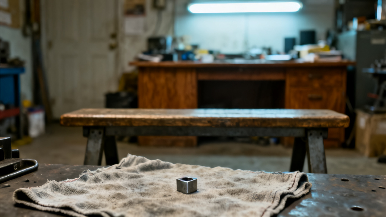
Two sheets are on the bench. One part is in the vise. Both sheets are clipped at the top left corner to your job number printed in neon orange ink, no stray marks or smudges to obscure the dimension fields you fill out next. The raw stock is 6061 aluminum, 1.25 inches thick, clamped dead square to the jaw faces so you don’t introduce runout when you run the first facing pass. You grab a fine point permanent marker and a set of digital calipers calibrated last shift, set them on the open space to your right within arm’s reach before you start up the milling machine.
First piece rough facing measurement entry for check sheet line 4
You run the first 0.05 inch rough facing pass across the top surface of the stock, shut off the spindle, and blow all excess chips away from the face with your air nozzle. Wipe the surface clean with a lint-free shop cloth to remove any leftover cutting fluid residue that could skew your measurement readings. Follow these steps to log your measurements accurately:

- Zero your calipers against the flat edge of the fixed vise jaw to confirm calibration holds at 0.000 inch before you take any readings.
- Take three separate thickness readings across the face of the first piece, spaced one inch apart at the left edge, right edge, and center point.
- Write each reading to the fourth decimal place in the blank fields on line 4 of the front check sheet, no rounding up or down before you log the number.
- Cross out any incorrect entries with a single straight line, initial next to the strike, and write the correct number immediately to the right, no white out or scribbling over errors.
Illustrative example: if your three readings come to 1.201, 1.202, and 1.201 inches, you log each as written, even if the average falls exactly in the middle of the allowed tolerance band.
Top check sheet hole position tolerance validation
You move the spindle to the first marked hole position 0.75 inches from the top left corner of the faced stock, drill a 0.201 inch pilot hole, then ream to the final 0.25 inch diameter. Blow the hole clear of chips, then run your pin gage through the opening to confirm it fits without wiggle or binding. You measure the distance from the left edge of the stock to the center of the hole with your depth mic, log the reading on line 7 of the top check sheet, then repeat the process for the remaining 7 holes across the top face. You cross reference each position against the printed CAD callout to make sure you don’t drift more than the allowed 0.0015 inch offset from the marked grid. You mark a small pencil dot next to each hole entry on the check sheet as you complete each measurement, so you don’t accidentally re-measure the same hole twice.
Lower check sheet thread depth confirmation for 1/4 NPT ports
You flip the first piece over in the vise, clamp it tight, face the reverse side to the same 1.200 inch finished thickness, then spot drill the four 1/4 NPT port positions on the reverse face. You tap each port with a tapered NPT tap, running cutting fluid at every half turn to avoid breaking the tap inside the stock. Blow each port clear of chips and cutting fluid, then insert your NPT plug gage to the first stop, mark how far the gage sits against the face of the first piece, and log the depth reading on line 12 of the lower check sheet. You make sure each thread cuts cleanly all the way to the bottom of the port, no burrs or raised edges around the opening that could cause a leak when the manifold is installed later. You do not force the gage further than it sits naturally, as that can warp the thread walls and give you a false positive reading.
Deburred first piece edge quality sign-off on both check sheets
You remove the first piece from the vise, run a 320 grit abrasive pad along all cut edges of the block to remove any sharp burrs left from milling and drilling operations. You run your bare finger along each edge to confirm no sharp spots remain, then wipe the entire part down with a clean shop cloth to remove all leftover abrasive dust and cutting fluid. You mark the edge quality check box on line 18 of the top check sheet, and line 16 of the lower check sheet, then initial each marked box to confirm you completed the step. You set the first piece on the clean section of the bench next to the two check sheets, so the shift lead can easily find both when they come over to witness your measurements.
Witnessed first piece dimensional sign-off section for both check sheets
You flag down the shift lead when they have a free moment, and walk them through each of your logged measurements, referencing the physical first piece to confirm all readings align with the numbers you wrote on both check sheets. You hand them your calibrated calipers so they can spot check three random measurements across the face, hole positions, and thread depths to cross reference your entries. The shift lead signs and dates the witness section on the bottom of both check sheets once they review all your entries. You clip the two check sheets together with the first piece in a clear plastic job bag, then set the bag on the shelf marked for held first piece approvals. You drop a copy of the signed top check sheet off at the Traveler Desk before you head back to your bench to prep for the full production run if this first piece moves forward.
Post-shift first piece check sheet reference when you pull this job back for the production run
When you come in for your next shift, you pull this job bag from the approval shelf, open the two check sheets first to confirm all sign-offs are in place before you load the next length of 6061 aluminum stock in the vise. You reference the marked tolerances you logged on the first piece check sheet to set your initial offsets for the production run, adjusting for any minor drift you noticed during the first piece cuts to keep all production parts within tolerance. You leave the check sheets clipped to the front of your machine guard under your work light, so you can reference them at any point during the run if you notice a measurement falls outside the expected band. You update the check sheets with production run counts at the end of each 10 parts, logging any adjustments you make to offsets or cutting speeds, so you have a full record of the run for future reference if the same part is ordered again later. You keep the first piece on the edge of your bench for the full duration of the production run, so you can compare any new parts directly against the approved sample if you notice inconsistencies in cut quality or measurement readings as you run each part.